RS232 Communication Protocol is a serial communication protocol that was developed in 1962 by EIA/TIA (Electronics Industry Alliance/Telecommunications Industry Association).
Innovative serial networking protocols such as USB, Ethernet, and Wi-Fi are used in modern hardware designs. RS232, on the other hand, has proved to be common. The explanation for this is that RS232 signals go further than I2C and serial TTL signals. It also has greater noise immunity. It has been known to work with computers and modems from a variety of manufacturers.
What exactly is the RS232 protocol?
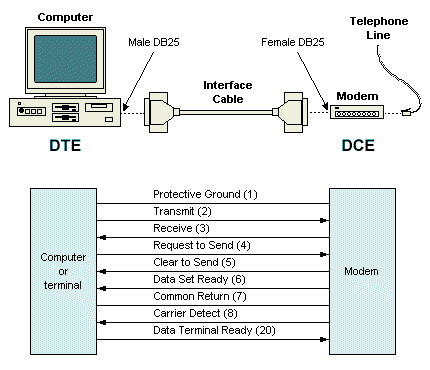
The letter ‘RS' stands for Recommended Standard in RS232. It specifies DTE and DCE signals for serial communication. DTE stands for Data Terminal Equipment, while DCE stands for Data Communication Equipment. A machine is an example of a DTE system, while a modem is an example of a DCE device. Informally, it is defined as the serial binary data exchange interface between DTE and DCE equipment. Figure 1 shows DTE and DCE as an example.
Figure 1. DTE and DCE Represantation
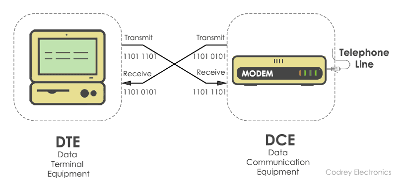
The knowledge is serially transmitted from the DTE (computer) to the DCE (other end equipment) (modem). Figure 2 illustrates how DTE and DCE sends informations each other.
Figure 2. DTE and DCE Communication
DTE sends binary data “11011101” to DCE, and DCE sends binary data “11010101” to the DTE unit in this situation in Figure 2.
The typical voltage levels, electrical standards, operation mode, and number of bits to be transferred from DTE to DCE are all defined by RS232. This norm governs the transfer of information over telephone lines.
Electrical Requirements
In 1969, the electrical requirements for RS232 were revised. Electrical voltages, slew rate, line impedance, operating mode, and baud rate are all defined.
Levels of Voltage
RS232's line voltages range from -25V to +25V. Signal voltage and power voltage are the two types.
Figure 3. Voltage Level of RS232
Figure 3 shows the level of voltage of RS232 and according to the figure, logic ‘1' is represented by signal voltages between +3V and +25V, while logic ‘0' is represented by signal voltages between -3V and -25V. Negative logic is used for control voltage signals, i.e., logic ‘1' indicates -3 to -25 volts and logic ‘0' indicates +3V to +25V. The voltage range of -3V to +3V is regarded as indeterminate.
Slew Rate
The rate at which the RS232 driver reacts is determined by the shift in input voltage. Slew rate is a term used to describe this. To minimize cross-talk between neighboring signals, the RS232 protocol establishes a minimum slew rate with gradual rise and fall times. The maximum slew rate allowed is normally 30V/μsec.
Figure 4. Slew Rate of a Signal
Above figure (Figure 4) demostrates what is slew rate is. Slew rate is the difference of voltage or current, or some other electrical amount, per unit of time in electronics. The unit of measurement is volts/second or amperes/second or the unit being addressed as expressed in SI units (but it is normally expressed in V/μs).
Line Impedance
To optimize the voltage transfer between the transmitter and receiver, the impedance bridging between the RS232 driver and the receiver is specified. It's anywhere between 3K and 7K.
Mode of Operation
Single-ended signaling is used by RS232 units (two wire). This ensures that one wire transmits a changing voltage while the other is grounded. Noise caused by variations in ground voltages of the driver and receiver circuits affects single-ended signals. The single-ended technique has the advantage of requiring fewer wires to relay data. Figure 5 shows the difference of differential and single-ended signal types by using circuit representation.
Figure 5. Single and Differential Type of Signals
Baud rate
The number of binary bits transferred per second is known as the bit rate. The baud rate ranges from 110 to 230400 on RS232. Baud rates of 1200, 4800, 9600, and 115200 are commonly used. It establishes the rate at which data will be transmitted from the transmitter to the receiver. Also, note that, baud rate must be same at both the transmitter side and receiver side.
Communication Interface
Using DB9 and DB25 connectors, RS232 defines connectivity between the DTE and DCE. Male and female D-sub connectors (DB9, DB25) are used. The DB9 connector has 9 pins, while the DB25 connector has 25, each with its own feature.
Figure 6. DB9 Connector
The serial COM port (DTE) on a computer is normally a male port, as seen below, and any peripheral devices you add to it are usually female (DCE). Figure 7 shows female and male type of DB9 connectors.
Figure 7. Male and Female type of DB9 Connectors
The RS232 connector was designed with 25 pins in mind. A secondary RS232 contact channel was used in this pin-out. Figure 8 illustrates the pin representation of DB25.
Figure 8. DB25 Pin Out
Functional Description
RS232 specified the functions of signals used in the serial interface in addition to their electrical characteristics. Common ground, data, power, and timing signals are among them. The following is a list of the signals that are used in the RS232 pinout.
| Signal Name | Function |
|---|
| Protective Ground | The chassis ground of the metallic connector is attached to this signal. |
| Common Ground | Both control signals have a zero reference voltage frequency. |
| TxD (Transmit Pin) | To send data from the DTE to the DCE. |
| RxD (Receive Pin) | Data is sent from DCE to DTE. |
| DTR (Data Terminal Ready) | DTE is prepared to take requests. |
| DCD (Data carrier Detect) | A carrier from a DTE in a distant area is accepted by DCE. |
| DSR (Data Set Ready) | DCE is ready to transmit and receive the data. |
| RI (Ring Indicator) | The incoming ring tone on the phone line is detected. |
| RTS (Request to Send) | DTE requests that DCE submit the results. |
| RTR (Ready to Receive) | DTE has been set up to collect data from DCE. |
| CTS (Clear To Send) | The DCE is ready to receive data from the DTE.. |
Aside from the aforementioned signals, RS232 supplies secondary signals such as secondary DTE, secondary RTS, secondary DCD, secondary TxD, and secondary RxD for optional DTE and DCE connections.
Types of Serial Cables
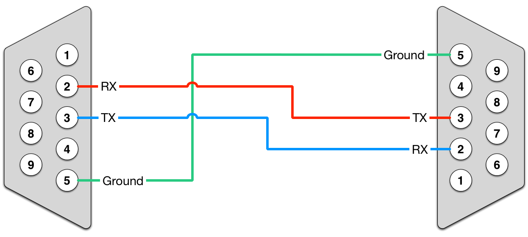
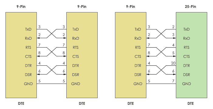
Two types of RS232 cables are available to provide serial communication between DTE and DCE. Null modem and Straight-cable are the two options. The TX (Transmitter) pin of the male connector is connected to the RX (Receiver) pin of the female, and the RX pin of the male is connected to the TX pin of the female in a null modem cable.
Figure 9. Null Modem or Crossover Cable
The Straight-through cable comes next. It's a one-to-one socket, which means that the transmit pin of one device connects to the transmit pin of another device, and the receiver pin of one device connects to the receiver pin of another device. Apart from ties, the wiring capacitance determines the cable length. The cable is approximately 80 feet long, as stated in the specification.
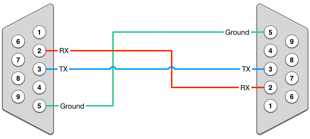
Figure 10. Straight-through Cable
How RS232 Communication Works?
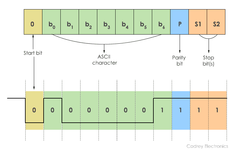
The protocol format should be used to understand how RS-232 works. Since RS-232 is a single-way point-to-point asynchronous communication protocol, data is sent only in one direction. The transmitter and receiver are synchronized without the use of a clock. The data format begins with a start bit, which is followed by 7-bit binary data, parity bit, and stop bit, all of which are sent in order.
Protocol Format
Figure 11. RS232 Framing
The transmission starts with a Start bit of ‘0.' Following that is 7 bits of ASCII results. For receiver validation, the parity bit is appended to this info. The data transmitted from the transmitter and the data received at the receiver should be identical. Finally, a stop bit, which is defined by the binary ‘1', is used to stop the transmission. In most cases, one or two stop bits can be sent.
Figure 12. RS232 Data Send
The ASCII character ‘A' is sent using a serial binary stream of ‘1s and 0s' in the diagram above. There should be a pause between each bit when sending data. The RS232 line is in a negative logic state, and this delay is called inactive period (-12V).
What is Handshaking?
The method of exchanging information signals between the sender (transmitter) and receiver is known as handshaking. Between the transmitter and receiver, these signals form a transmission channel. There are two forms of handshaking in RS232. Hardware and machine handshaking are the two types of handshaking.
Figure 13. Handshaking in RS232
The DB9 and DB25 connectors are used for handshaking. Just the TxD (Transmitter) and RxD (Receiver) are cross-coupled while no handshaking is done. RTS, CTS, DSR, and DTR are attached in a loopback manner to the other pins. RTS and CTS are cross-coupled in order to use the handshaking technique. In addition, DTR and DSR are linked in cross mode.
Why to use Handshaking?
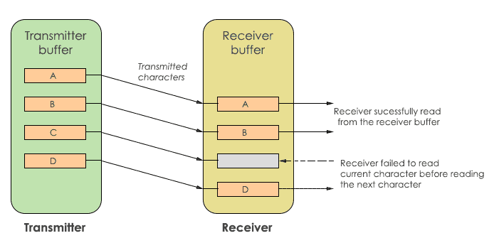
It is crucial to ensure reliable contact between the transmitter and receiver in order to send and receive data without losing data. Buffer is used to do this. Buffering is a temporary storage area that requires the sender and receiver to store data before they are read at separate rates by each other.
Figure 14. Data Flow
The transmitter and receiver each have their own buffer in the diagram Figure 14. The characters to be transmitted to the receiver are stored in the transmit buffer. The characters received from the transmitter are stored in the receive buffer. If the transmitter sends data at a faster rate than the receiver, the receiver will be unable to retrieve it. Character ‘C' is ignored by the recipient in this situation. Handshakes are used to prevent this. Handshaking requires the transmitter and receiver devices to confirm their agreement before transmission begins.
Hardware Handshaking
Hardware handshaking is used to monitor the flow of data transmission and receipt. It uses the DTR, DSR, RTS, and CTS control signals. RTS and CTS signals are typically used to create contact between a device and a modem. It prevents the data in the receiver buffer from being substituted. To trigger handshaking, the signals are held at a high level (logic ‘1).
Software Handshaking
For start-stop conversation, this form of handshaking uses two ASCII characters. As a result, this is referred to as device flow management. The serial contact is regulated by the XON/XOFF character in software handshaking. Ctrl+S or ASCII character 11 is represented by ‘XON,' while Ctrl+Q or ASCII 13 is represented by ‘XOFF.' Three wires are required for this handshaking. TXD, RXD, and signal GND are the three. When the ‘XOFF' character is activated, the connection is shut down before the sender receives the ‘XON' character. The receiver buffer may become overloaded in some situations, causing the receiver to send ‘XOFF' to the transmitter automatically.
How Handshaking Works?
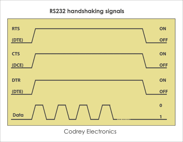
The DTE pulls the RTS line high to wake up the DCE in the initial state. There is no data transmission in this state. DCE then sets the CTS line to HIGH in order to obtain the results. This causes the DTE to react and the DTR to be set to HIGH. The data migration is now underway. DTE pulls both RTS and DTR LOW after data transmission is complete. The CTS line is then triggered to the LOW state by DCE. This disables the DTE's ability to relay data.
Figure 15. Handshaking Signals in RS232
Handshaking is initiated by a DTE order, which takes care of the contact connection and allows the DCE to transfer data.
Difference between RS232 and UART
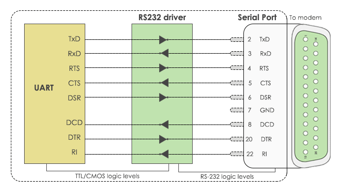
The voltage levels are the main difference between the RS232 and UART protocols. They both embrace half-duplex and full-duplex communication, apart from that. Microcontrollers are sensitive to RS232 voltages and may be affected as a result. UART (Universal Asynchronous Transmitter Receiver) is used to prevent this. It uses serial communication to send and receive data. Between the UART and the serial port, an RS232 driver IC such as MAX232 is used to convert voltage levels.
Figure 16. RS232 and UART
Advantages
The benefits of RS232 include its use as a standard serial interface for device to system connectivity and the following advantages.
- Simple protocol design.
- Hardware overhead is lesser than parallel communication.
- Recommended standard for short distance applications.
- DTE and DCE connectivity are supported.
- For growth, a low-cost protocol is used.
Disadvantages
The RS232 protocol has two drawbacks: it does not allow full-duplex communication and it is a single-ended protocol that causes ground potential to change. Furthermore, during serial conversation, the longer cable duration introduces cross chat. As a result, this protocol is only suitable for long-distance correspondence.
Submissions
The RS232 protocol is used in a variety of applications. Here are a few examples:
- Teletypewriter devices.
- Demodulator applications.
- PC COM port interfacing.
- In embedded systems for debugging.
- Modems and printers.
- Handheld equipment.
- CNC controllers, Software debuggers etc.
- Barcode scanners and Point of Sales (POS) terminals.
